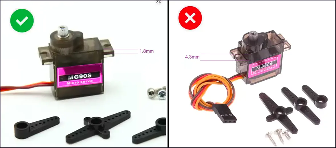
Placing and Soldering the Components
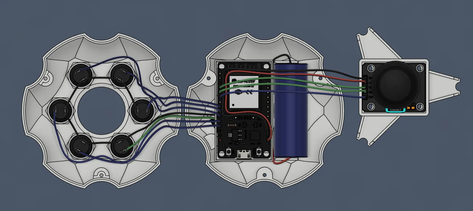
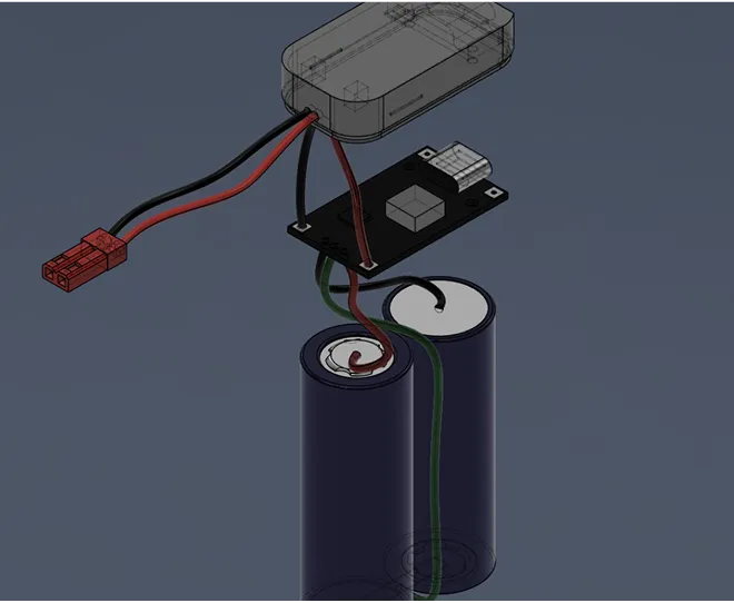
Open the file — this is the complete wiring diagram. Make sure you understand where the power, buttons, and joystick go.
Refer to file
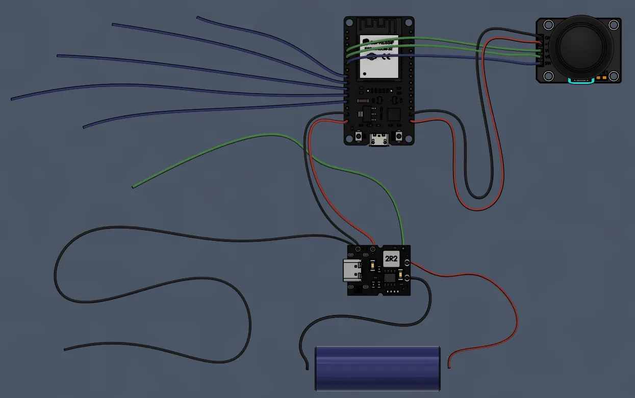
Picture 2. #1 rc-wires-length file
According to the diagram, VCC, GND, VRx, VRy, and SW correspond to ESP32 pins. Check polarity before soldering to a battery.
Each button is a separate GPIO + common ground. Check the placement in file
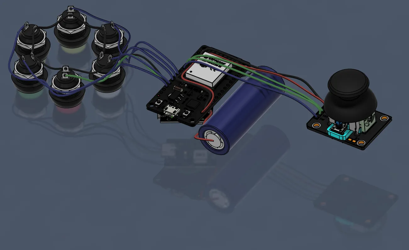
Картинка 3. #2 rc-wires-in-place file
Battery → DC-DC charging module → 5V to ESP32. Before turning it on for the first time, check the output voltage with a multimeter.
No bare contacts.
No crossed plus/minus.
The wires should not be pulled.
After that, you can proceed to laying the wires in the housing.
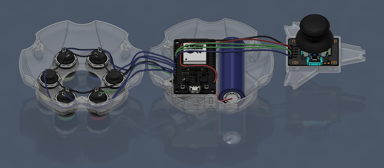
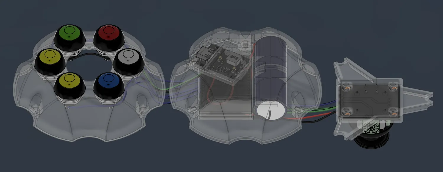
Pictures 4 & 5. laying the wires in the housing
.png)